Parallel Circuit Wiring
Wiring electrical elements in parallel means that each will have its own distinct loop. Therefore, there are multiple paths through which current can flow.

Where
R1 & R2: Resistors
V: Voltage Source
I1, I2 & I3: Current Values
Contents |
In the circuit diagram below, each resistor is wired directly and independently to the voltage source. If either resistor were removed - thereby creating an open circuit across one of the loops - current would still be able to flow across the other resistor. The total voltage drop in each loop must be equal to the voltage supplied to the loop. Therefore, in a circuit like the one displayed below where a single voltage source delivers voltage to several loads wired in parallel, the voltage drop across each will be the same.

Where
V: Voltage Source
R1 & R2: Resistors
V1 & V2: Voltage drop across each resistor
V = V1 = V2
When two voltage sources are wired in parallel, the positive terminal of one source is wired to the positive terminal of the other. The voltage provided by each source are therefore not added to one another - the voltage delivered to the circuit is equal to the voltage of the individual sources. Therefore, voltage sources that are wired together in parallel need to have the same voltage.

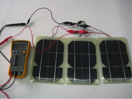
If the two voltage sources in the parallel above are 3-Volt photovoltaic modules, the total voltage across the resistor would be 3 Volts. In this configuration the positive (red) lead of the first module is wired to the positive lead of the next and the negative (black) lead of the first to the negative lead of next. Notice that in the schematic there is a connection between the positive side of the two sources and between the negative side. No matter how many 3-Volt photovoltaic modules are wired together in this configuration, the voltage delivered to the resistor will always be 3-Volts.

Vtotal = V1 = V2 = V3 = ... = Vn
In a parallel circuit there are multiple paths across which current can flow, and it will divide according to the resistance in each branch. The total current in the circuit must still be conserved, and so when it divides (or combines) at a junction, the sum of the current entering that junction will be equal to the sum of current leaving it.

I1 = I2 + I3
I3 = I4 + I5
Therefore, when several voltage sources are wired together in parallel, the voltage will not add, but the current delivered by each of those voltage sources will.

